Ceci est une ancienne révision du document !
Rotor 36
About
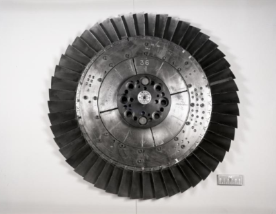
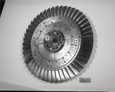
Rotor 36 is part of a research program to study a advanced-core compressor design with a high compression ratio (20:1). It is therefore the second stage rotor of this eight stage transonic compressor. Of these eight stages, the first four have been designed and tested : rotors 35, 36, 37 and 38. For more information, here is a link to a report from NASA.
- Original technical report [1]:
@TechReport{reid1982design, author = {Reid, L. and Moore, R. D.}, date = {1982}, institution = {NASA Lewis Research Center Cleveland, OH, United States}, title = {Performance of single-stage axial-flow transonic compressor with rotor and stator aspect ratios of 1.63 and 1.78, respectively, and with design pressure ratio of 1.82}, number = {NASA-TP-1974}, url = {https://ntrs.nasa.gov/citations/19820011348}, } - Pictures :
@Misc{huebler1977records,
author   = {Huebler, D.},
title    = {Rotor 36 assembly and stator 36 casing half. {R}ecords of the {N}ational {A}eronautics and {S}pace {A}dministration, 1903 - 2006. {P}hotographs relating to agency activities, facilities and personnel, 1973 - 2013},
note     = {\href{https://catalog.archives.gov/id/17467913}{https://catalog.archives.gov/id/17467913}, 1977 }, % for Fig. 1}
note     = {\href{https://catalog.archives.gov/id/17467884}{https://catalog.archives.gov/id/17467884}, 1977 }, % for Fig. 2}
Useful documents
- downloadable models (Git project)
- NASA technical report (.pdf)
- geometrical parameters file (.csv), usable as input of OpenMCAD[2] to generate reference blade models.
Reference blade
The reference blade is defined with multiple-circular arc profiles[3] given in the original NASA report[1]. Corresponding models are computed with the open-source code OpenMCAD[2].
Geometry
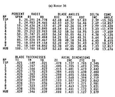
The geometry of rotor 36 is described in the original NASA report by the following tables. The length are in centimeters and the angles in degrees.
Aerodynamic design
| unit | value | |
|---|---|---|
| pressure ratio | [-] | 1.82 |
| mass flow | [kg/s] | 20.2 |
| tip speed | [m/s] | 455 |
| tip solidity | [-] | 1.3 |
| aspect ratio | [-] | 1.63 |
| number of blades | [-] | 48 |
| rotative speed | [rad/s] | 1800 |
Material properties
Rotor 36 is made of a 200-grade maraging steel[4], but the exact material properties are not provided in the NASA report. The following properties are considered:
| unit | value | |
|---|---|---|
| alloy | [-] | 18-Ni-200-maraging |
| Young's modulus | [GPa] | 180 |
| density | [kg/m3] | 8000 |
| Poisson's ratio | [-] | 0.3 |
| yield stress | [GPa] | 1.38 |
CAD model
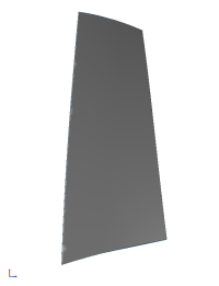
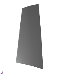
The CAD model is computed with the open source code OpenMCAD[2].
Natural frequencies
First three natural frequencies (with clamped root) for the mesh computed with OpenMCAD[2]:
| Mode | Type | Natural angular frequency (rad/sec) | Natural frequency (Hz) |
|---|---|---|---|
| 1 | 1B | 3525.61 | 561.119 |
| 2 | 1T | 12882.23 | 2050.27 |
| 3 | 2B | 14256.42 | 2268.98 |
Initial blade
The initial blade is defined with in-house LAVA parameters[5] computed from the reference blade CAD model. The initial blade is usually used as starting point for an optimization process. Its geometry is similar to the one of the reference blade.
Natural frequencies
First three natural frequencies (with clamped root)
- from the whole mesh:
| Mode | Type | Natural angular frequency (rad/sec) | Natural frequency (Hz) |
|---|---|---|---|
| 1 | 1B | 3538.38 | 563.15 |
| 2 | 1T | 12965.60 | 2063.54 |
| 3 | 2B | 14395.72 | 2291.15 |
- from the reduced order model:
| Mode | Type | Natural angular frequency (rad/sec) | Natural frequency (Hz) |
|---|---|---|---|
| 1 | 1B | 3538.56 | 563.18 |
| 2 | 1T | 12969.75 | 2064.2 |
| 3 | 2B | 14407,6 | 2293.04 |
À propos
Le rotor 36 appartient à un programme de recherche visant à étudier une conception de compresseur possédant un grand taux de compression (20:1). Il est donc le rotor du deuxième étage de ce compresseur transsonique de huit étages. Parmi ces huit étages, les quatre premiers ont été conçus et testés, ils correspondent aux rotors 35, 36, 37 et 38. Pour plus d'information, voici un lien vers un rapport de la NASA.
- Rapport technique original [1]:
@TechReport{reid1982design, author = {Reid, L. and Moore, R. D.}, date = {1982}, institution = {NASA Lewis Research Center Cleveland, OH, United States}, title = {Performance of single-stage axial-flow transonic compressor with rotor and stator aspect ratios of 1.63 and 1.78, respectively, and with design pressure ratio of 1.82}, number = {NASA-TP-1974}, url = {https://ntrs.nasa.gov/citations/19820011348}, } - Photographies :
@Misc{huebler1977records,
author   = {Huebler, D.},
title    = {Rotor 36 assembly and stator 36 casing half. {R}ecords of the {N}ational {A}eronautics and {S}pace {A}dministration, 1903 - 2006. {P}hotographs relating to agency activities, facilities and personnel, 1973 - 2013},
note     = {\href{https://catalog.archives.gov/id/17467913}{https://catalog.archives.gov/id/17467913}, 1977 }, % pour Fig. 1
note     = {\href{https://catalog.archives.gov/id/17467884}{https://catalog.archives.gov/id/17467884}, 1977 }, % pour Fig. 2}
Documents utiles
- modèles téléchargeables (lien vers projet Git)
- rapport technique original de la NASA (.pdf)
- fichier de paramètres géométriques (.csv), utilisable en entrée de OpenMCAD[2] pour générer l'aube de référence
Aube de référence
L'aube de référence est définie par des profils de type arcs circulaires multiples[3], donnés dans le rapport technique original de la NASA[1]. Les modèles associés sont obtenus avec le code en libre accès OpenMCAD[2].
Géométrie
La géométrie du rotor 36 est décrite dans le rapport d'origine de la NASA par les tableaux suivants. Les grandeurs sont en centimètres et en degrés.
Caractéristiques aérodynamiques
| unités | valeurs | |
|---|---|---|
| taux de compression | [-] | 1,82 |
| débit massique | [kg/s] | 20,2 |
| vitesse en tête | [m/s] | 455 |
| solidité en tête | [-] | 1,3 |
| allongement | [-] | 1,63 |
| nombre d'aubes | [-] | 48 |
| vitesse de rotation | [rad/s] | 1800 |
Propriétés matériau
Le matériau du rotor 36 est un alliage à base de nickel : un acier maraging de grade 200[4], mais ses caractéristiques ne sont pas fournies dans le raport de la NASA. Les propriétés considérées sont :
| unité | valeurs | |
|---|---|---|
| alliage | [-] | 18-Ni-200-maraging |
| module d'Young | [GPa] | 180 |
| masse volumique | [kg/m3] | 8000 |
| coefficient de Poisson | [-] | 0,3 |
| limite élastique | [GPa] | 1,38 |
Modèle CAO
Le modèle CAO est obtenu avec OpenMCAD[2].
Fréquences propres
Fréquences des trois premiers modes (noeuds du pied d'aube encastrés) pour le maillage obtenu avec OpenMCAD[2] :
| Mode | Type | Pulsation propre (rad/sec) | Fréquence propre (Hz) |
|---|---|---|---|
| 1 | 1F | 3525,61 | 561,119 |
| 2 | 1T | 12882,23 | 2050,27 |
| 3 | 2F | 14256,42 | 2268,98 |
Aube initiale
L'aube initiale est définie par des paramètres spécifiques au LAVA[5] obtenus à partir du modèle CAO de l'aube de référence. L'aube initiale est classiquement utilisée comme point de départ dans le cadre de procédures d'optimisation; sa géométrie est similaire à celle de l'aube de référence.
Fréquences propres
Fréquences des trois premiers modes (noeuds du pied d'aube encastrés),
- pour le maillage complet :
| Mode | Type | Pulsation propre (rad/sec) | Fréquence propre (Hz) |
|---|---|---|---|
| 1 | 1F | 3538,38 | 563,15 |
| 2 | 1T | 12965,60 | 2063,54 |
| 3 | 2F | 14395,72 | 2291,15 |
- pour le modèle réduit :
| Mode | Type | Pulsation propre (rad/sec) | Fréquence propre (Hz) |
|---|---|---|---|
| 1 | 1F | 3538,56 | 563,18 |
| 2 | 1T | 12969,75 | 2064,2 |
| 3 | 2F | 14407,6 | 2293,04 |
